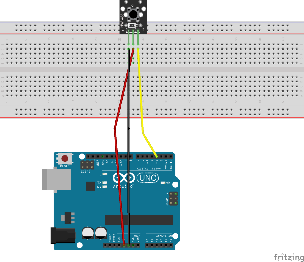
For this project we’ll connect up the Button Sensor and turn the built in LED on when it is pressed. For the simplest version of this project, you’ll use the HW-483 (Push) Button Module and 3 wires. Once you see it working, you can modify it so that you use the power rails on the breadboard. That will make it easier to integrate this setup with other projects.
// Sketch for HW-483 Button Sensor with pull-up resistor configuration
// Component:
// Tutorial:

// Change to the pin number that the Button module "S" pin is connected to
#define BUTTON_PIN 3

void setup() {
  pinMode(BUTTON_PIN, INPUT);         // button pin (S) set to input
  pinMode(LED_BUILTIN, OUTPUT);       // on-board LED, typically pin 13
}

void loop() {
  if (!digitalRead(BUTTON_PIN)) {       // is the switch closed?
    // switch closed with pull-up resistor
    delay(50);                        // switch debounce delay
    while (!digitalRead(BUTTON_PIN)); // wait for switch to open
    digitalWrite(LED_BUILTIN, HIGH);  // turn LED on
    delay(1000);                      // leave LED on for 1 second
  } else {
    // switch open with pull-up resistor
    digitalWrite(LED_BUILTIN, LOW);   // switch LED off
  }
}